ASSIGNMENT 2 - THE 1:1 FUEL TANK [40%]
THE 1:1 FUEL TANK - YAMAHA IT250 PETROL TANK
 |
Our next assignment which is worth 40% of our final assessment mark consisted of a group of 10 team members to work towards constructing a 1:1 scale template replicating a motorcycle fuel tank, and then divide it into thirds. Each individual is also required to create an aluminum skin to adhere the third of its contour. In order to achieve this task, it requires all team members to utilise the skills they have gained in previous projects and replicate the fuel tank as closely as possible to the existing fuel tank model.
Below is the list of team members in my group:
- Amity Wattle
- Ben Mitchel
- Charlie Mcleod
- Conrad To
- Emma La Coste
- Jake Fornasaro
- Monica Badr (Me)
- Remy Dunne
- Simon Cooper
- Thomas Surmon
There were three different types of fuel tank models presented to us. Russell explained the complexity of each model and ranked which fuel tank will be most difficult to construct. Our group gathered together and we all came to the agreement to work on the below tank known as the "Yamaha IT250" shown in figure 1.1, which is the hardest model to replicate due to the deep curves and different hammering techniques required to achieve creating this fuel tank. The tank We all decided we would like to be challenged and see if we could accomplish this task and test our abilities.
 |
| FIGURE 1.1 - Displays the fuel tank model our group decided to choose [Yamaha IT250] |
In order to prepare for the laser cutting machine/CNC machinery we were required to take as many photos of the fuel tank and ensure every angle is captured. This stage is very crucial as it initiates whether our template will be successful. A technique we needed to account for was lighting, this was suggested by Daniel, for example when taking photos it is important to ensure the same lighting is replicated, and photos are not taken at different times, it must be consistent. Another suggestion we accounted for was to apply masking tape in order for recap to recognise the photos when uploading them. Once we accomplished taking as many pictures we upload them onto recap however this failed numerous time and our model was not being recognised by the program, shown in figure 1.2 below.
 |
| FIGURE 1.2 - Recap unable to recognise the images taken, when uploaded. |
We organised to go back to the workshop and take more photos, this was a success as the program was able to combine the photos we took and replicated the fuel tank. This stage was very time consuming.
TASK 2 - EXPORTING 3D MODEL ONTO AUTODESK SLICER FOR FUSION 360
The next stage of this project, was to import our 3D model onto Autodesk slicer for fusion 360. This was to prepare creating our template for the fuel tank via the laser cutting machine. Slicer reported that we required 13 pieces of timber sheets to create our templates. Once we were aware of the number of sheets we required, we exported the files onto illustrator, where we were able to rectify any defects. For example we noticed some openings within our boundary lines and closed them up. Following on we decided to test the laser cutting machine and see if the spacing is good, and the pieces interlock well together.
Unfortunately the spacing/width were too wide and when inserting the pieces together it was loose, therefore we needed to go back onto slicer and adjust the spacing size. Originally it was 3mm spacing, however we noticed when exporting it onto illustrator the spacing size increases around double in size, as shown in figure 1.3. We trialed different sizing and agreed for the spacing to be roughly between 1.5mm, as the template interlocked best with this size.
 |
| FIGURE 1.3 - Shows the spacing of the template pieces are too wide and when interlocking them, they slide off. |
TASK 3 - LASER CUTTING
Once we ensured all defects were rectified, we exported our 13 sheets into a PDF format to begin laser cutting. We ensured all the correct settings were applied onto illustrator. For example boundary lines were outlined in the colour RED, for the laser cutting machine to cut around the desired lines we needed to be cut. We placed 13, 3mm plywood sheets into the laser cutting machine (Fusion 360). This process was about 45 minutes to complete, we utilised 2 laser cutting machine at a time, to increase productivity and efficiency, shown in Figure 1.4.
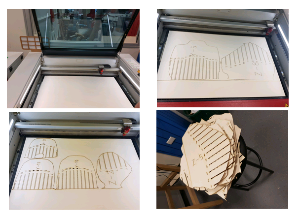 |
| FIGURE 1.4 - Shows the plywood being placed in Fusion 360 to begin laser cutting. |
TASK 4 - CREATING THE TEMPLATE
Once we completed combining laser cutting our templates, we then interlocked them all together. This task was achieved via using the slicer, which illustrates which pieces correspond to each other. For example, piece Y - 12 is joined with Z - 6. Figure 1.4 below shows progress shots of combining the pieces together.
TASK 5 - CREATING CONTOUR LINE USING MASKING TAPE
Following on, once we combined the pieces together, Daniel suggested we create contour lines using masking tape and covering the whole of the fuel tank. Shown in below figure 1.5. This significantly help determine the curves and labeling the depth of certain sections. It also gives an overall view of what hammering techniques we should do to each different section of the tank.
TASK 6 - OUTLINING THE FUEL TANK AND USING A3 PAPER/ HAMMERING THE MODEL
Once we completed taping the whole of the tank, we were able to trace the curves using A3 paper and use that as a reference to cut our aluminium. By tracing the curves this reduces damaging the template if we were to hammer onto it, as the template is quite fragile. The paper was then transferred onto an aluminium sheet and began to trace the trace the shape. We decided the tank will be composed of 6 aluminium pieces. I chose to construct the middle part of the tank, shown in diagram below. The dimensions of the aluminium sheet that needed to be cut were 14cm x 37cm. The diameter of the figure shown below was 8cm. Once the sheet was cut out, I bent the metal sheet, this was completed to allow for a more defined curve. Next using a nylon mallet, I began to hammer the mid section, I continued this until I was satisfied with the outcome. Following on, to create the round edges shown below, I layed the metal sheet on a round metal log and used the nylon mallet and began to hammer down, same technique used when creating the torus. I then shrunk along the sides. Finally to remove any bumps, I rolled it on the english wheel, this allowed for a smooth finish.
TASK 7 - PUTTING ALL THE ALUMINIUM PIECES TOGETHER
The final task was to combine all of the aluminium pieces together and observe whether the pieces match. This was a success.
 |
| FIGURE 1.4 - Shows the pieces being combined to create the template |
TASK 5 - CREATING CONTOUR LINE USING MASKING TAPE
Following on, once we combined the pieces together, Daniel suggested we create contour lines using masking tape and covering the whole of the fuel tank. Shown in below figure 1.5. This significantly help determine the curves and labeling the depth of certain sections. It also gives an overall view of what hammering techniques we should do to each different section of the tank.
 |
| FIGURE 1.5 - Illustrates our group contouring the template |
Once we completed taping the whole of the tank, we were able to trace the curves using A3 paper and use that as a reference to cut our aluminium. By tracing the curves this reduces damaging the template if we were to hammer onto it, as the template is quite fragile. The paper was then transferred onto an aluminium sheet and began to trace the trace the shape. We decided the tank will be composed of 6 aluminium pieces. I chose to construct the middle part of the tank, shown in diagram below. The dimensions of the aluminium sheet that needed to be cut were 14cm x 37cm. The diameter of the figure shown below was 8cm. Once the sheet was cut out, I bent the metal sheet, this was completed to allow for a more defined curve. Next using a nylon mallet, I began to hammer the mid section, I continued this until I was satisfied with the outcome. Following on, to create the round edges shown below, I layed the metal sheet on a round metal log and used the nylon mallet and began to hammer down, same technique used when creating the torus. I then shrunk along the sides. Finally to remove any bumps, I rolled it on the english wheel, this allowed for a smooth finish.
 |
| FIGURE 1.6 - Item I chose to create for the Fuel tank |
 |
| FIGURE 1.6 - Finished Item |
The final task was to combine all of the aluminium pieces together and observe whether the pieces match. This was a success.
 |
| FIGURE 1.7 - Shows combined pieces |

Comments
Post a Comment